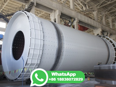
ball mill 3d diagram

Ball Mill | 3D CAD Model Library | GrabCAD

Ball Mill | 3D CAD Model Library | GrabCAD

WEBNov 25, 2016 · Ball Mill | 3D CAD Model Library | GrabCAD. Join 9,330,000 engineers with over 4,840,000 free CAD files. The CAD files and renderings posted to this website are created, uploaded and managed by thirdparty community members.

"ball mill" 3D Models to Print

WEBfree Downloads. 10000+ "ball mill" printable 3D Models. Every Day new 3D Models from all over the World. Click to find the best Results for ball mill Models for your 3D Printer.

The Anatomy of a CNC Machine: Exploring the CNC Block Diagram .

The Anatomy of a CNC Machine: Exploring the CNC Block Diagram .

WEBThe movement in a CNC machine is commonly controlled by linear guides, servo motors, and ball screws. Servo motors precisely move the ball screw nut to position different mechanical components, such as the spindle and the bed. Linear guides ensure that the movement of the bed and spindle is accurate and minimizes any potential play or .

A New Preparation Method for 3D Biocomposite Filament

A New Preparation Method for 3D Biocomposite Filament

WEBDec 20, 2022 · This study created a composite polymer for 3D from agave byproduct using mechanical alloying process. The cold milling technique used by the ball mill is a standard procedure to homogenize metallic mixtures. ... A mathematical and experimental dynamical phase diagram for ballmilled Ni10Zr7. J Alloys Compd .

MolView

MolView

WEBMolView consists of two main parts, a structural formula editor and a 3D model viewer. The structural formula editor is surround by three toolbars which contain the tools you can use in the editor. Once you've drawn a molecule, you can click the 2D to 3D button to convert the molecule into a 3D model which is then displayed in the viewer.

Ball Mill Design/Power Calculation

Ball Mill Design/Power Calculation

WEBJun 19, 2015 · The basic parameters used in ball mill design (power calculations), rod mill or any tumbling mill sizing are; material to be ground, characteristics, Bond Work Index, bulk density, specific density, desired mill tonnage capacity DTPH, operating % solids or pulp density, feed size as F80 and maximum 'chunk size', product size as P80 and .

Stirred mills

Stirred mills

WEBStirred mills global website

Ball mill for cement grinding

Ball mill for cement grinding

WEBCement grinding with our highly efficient ball mill. An inefficient ball mill is a major expense and could even cost you product quality. The best ball mills enable you to achieve the desired fineness quickly and efficiently, with minimum energy expenditure and low maintenance. With more than 4000 references worldwide, the FL ball mill is ...

The schematic diagram of a ball mill driveline.

The schematic diagram of a ball mill driveline.

WEBView. Download scientific diagram | The schematic diagram of a ball mill driveline. from publiion: Electromechanical Dynamic Behaviour and StartUp Evaluation of Tumbling Ball Mills | This ...

(PDF) Design of Threechamber Ball Mill

(PDF) Design of Threechamber Ball Mill

WEBJan 1, 2021 · Comchambered with the design of Φ × 13m threechamber ball mill, the design process of ball mill is described in detail. ... This paper focus on the key technologies involved in 3D SLAM of ...

Fig. 2 (a) Schematic diagram for the planetary ballmill showing...

Fig. 2 (a) Schematic diagram for the planetary ballmill showing...

WEBDownload scientific diagram | (a) Schematic diagram for the planetary ballmill showing movement of a milling vessel and planetary disks in a clockwise and counter clockwise direction. (b) A ...

Microstructure and Properties of MnCuBased Damping Alloys

Microstructure and Properties of MnCuBased Damping Alloys

WEBApr 16, 2019 · A MnCubased damping alloy with a nominal composition of 70Mn24Cu3Zn3Al (at.%) was prepared by ball milling of pure elemental powders and subsequent hotpress sintering of powder mixture at 750 and 825 °C for 2 h. For comparison, this alloy was also prepared by induction melting technology and then homogenized at 850 °C for .

Producing Metal Powder from Machining Chips Using Ball Milling .

Producing Metal Powder from Machining Chips Using Ball Milling .

WEBJun 27, 2023 · The optimum ball mill parameters to achieve a small particle size of µm include a ball mill speed of 500 rpm, a milling time of 10 h, and a balltopowder ratio (BPR) of 10:1. These settings are sufficient for obtaining better results.

ball mill 2000x4000 mm | 3D CAD Model Library | GrabCAD

ball mill 2000x4000 mm | 3D CAD Model Library | GrabCAD

WEBDec 4, 2019 · The GrabCAD Library offers millions of free CAD designs, CAD files, and 3D models. Join the GrabCAD Community today to gain access and download! Learn about the GrabCAD Platform ... ball mill 2000x4000 mm ball mill 2000x4000 mm / Loading ... GMM 355 M (2) AYAKLI (B3) sldprt. December 4th, 2019 DEG .

Find 3D shapes and stencils

Find 3D shapes and stencils

WEBBrowse your diagram type. Some diagram types, such as FlowChart, Maps, and Network, have builtin stencils of 3D shapes. Browse for some in the Shapes window—click More Shapes, then point to the diagram type you're creating. Look for "3D" in the stencil name. Use Shapes search. In the Shapes window, click Search. Enter 3D in the search ...

Synthesis of Metal Organic Frameworks by BallMilling

Synthesis of Metal Organic Frameworks by BallMilling

WEBIn this paper, the influencing factors of the synthesis of MOFs by ball milling are systematically reviewed ( Figure 1 ), including the effect of auxiliary additives, metal source type, ligand type, and reaction conditions, and the future outlook of development will be discussed. Figure 1. Scheme of the synthesis of metal organic frameworks by ...

Quantum Nanostructures (QDs): An Overview

Quantum Nanostructures (QDs): An Overview

WEBJan 1, 2018 · Schematic diagram for quantum nanostructures; bulk material, quantum well, quantum wire, quantum dot. ... breaking, or etching bulk materials into small pieces of nanometer dimension. This can be further divided into ball milling, lithography, and other processes. ... 3D assembly of semiconductor and metal nanocrystals: hybrid .

CNC Milling

CNC Milling

WEBMay 8, 2020 · A common milling operation to produce convex and concave parts. The process includes 3 steps – roughing, semifinishing and finishing. Roughing uses round inserts to do the initial work for removing most of the material. Ballnose end mills are the perfect fit for semifinishing and finishing.

Appliion of model predictive control in ball mill grinding circuit

Appliion of model predictive control in ball mill grinding circuit

WEBSep 1, 2007 · The schematic diagram of MPC applied in ball mill grinding circuit. All the signals from or to the grinding process are intercollected through digitaltoanalog or analogtodigital interfaces in a distributed control system (DCS) as shown in Fig. 9. This system works in a hierarchical manner through fiber optical communiions.

Schematic diagram of the planetary ball mill

Schematic diagram of the planetary ball mill

WEBDownload scientific diagram | Schematic diagram of the planetary ball mill from publiion: Effects of the friction coefficient of a barrel on the grinding performance of a planetary ball mill ...

Ball Milling

Ball Milling

WEBBall milling is a mechanical technique that is broadly used to grind powders into fine particles [134–141]. The reactants are generally broken apart using solvent molecules in the traditional method; but in ball milling, reactants are broken by using mechanical forces. The term mechanochemistry has been introduced very recently [142].

Ball Mill.

Ball Mill.

WEBOct 5, 2021 · Diagram: Construction: The mill consists of a hollow cylinder fixed on a metallic frame in such a way that it can rotate around its horizontal axis. The cylinder contains metallic balls occupying around 30 to 50% of total capacity. The balls are usually made up of rubber, porcelain or metal. The metallic balls are coated with chrome.

Rolling ball method for blend and resultant blend surface

Rolling ball method for blend and resultant blend surface

WEBDownload scientific diagram | Rolling ball method for blend and resultant blend surface from publiion: Remaining Stock Computation for 3DMachining in Parametric Regime | In manufacturing, it ...

QUICK TIP: How to machine 3D chamfers

QUICK TIP: How to machine 3D chamfers

WEBOct 24, 2017 · Select a ball endmill as the tool. In the Passes tab, select the outside edges of the chamfer as the Machining Boundary and set the Additional Offset to inches. Enable Contact Point Boundary, set the Boundary Overlap to 0 inches. In the Passes tab, set the Tolerance to inches. Set the Stepover to 3 times the width of the chamfer.

Author: Subject: Ball Mill (3D printed parts)

Author: Subject: Ball Mill (3D printed parts)

WEBMay 18, 2022 · Sciencemadness Discussion Board » Engineering and Equipment » Reagents and Apparatus Acquisition » Ball Mill (3D printed parts)

Solved (55) 3. A wet ball milling operation is used to

Solved (55) 3. A wet ball milling operation is used to

WEBA wet ball milling operation is used to grind crude ore into smaller particles of a desired size classifiion. As shown in the diagram below a slurry of crude ore and water (Stream 1) is fed into a ball mill along with a recycle stream (Stream 2). The mill product (Stream 3) is sent to a mechanical classifier where additional water ...

Ball Mill Working Principle, Construction, Appliions, .

Ball Mill Working Principle, Construction, Appliions, .

WEBIn a continuously operated mill, as shown in the diagram, the outlet is normally covered with a coarse screen to prevent the escape of the balls. Ball Mill Working Principle In the case of a continuously operated ball mill, the material to be ground is fed from the left through a 60° cone, and the product is discharged through a 30° cone to ...

Improving the wear resistance of 440 C bearing steel balls through ...

Improving the wear resistance of 440 C bearing steel balls through ...

WEBMar 1, 2024 · Afterward, the tempered steel balls underwent rigorous grinding and a refining process. The schematic diagram of steel ball treatment is depicted in Fig. 1, where a planetary ball mill (QM3SP2, Chishun Tech, China) equipped with a homemade grinding jar is used for surface treatment of the steel balls. Three experimental groups have been ...

Ball mill | 3D CAD Model Library | GrabCAD

Ball mill | 3D CAD Model Library | GrabCAD

WEBNov 30, 2014 · Ball mill | 3D CAD Model Library | GrabCAD. Join 9,280,000 engineers with over 4,820,000 free CAD files Join the Community. The CAD files and renderings posted to this website are created, uploaded and managed by thirdparty community members.

Ball Milling

Ball Milling

WEBBall milling technique, using mechanical alloying and mechanical milling approaches were proposed to the word wide in the 8th decade of the last century for preparing a wide spectrum of powder materials and their alloys. In fact, ball milling process is not new and dates back to more than 150 years. It has been used in size comminutions of ore, .

Ball Mills

Ball Mills

WEBRetsch offers mills with jar capacities from ml up to 150 l and balls are available from mm to 40 mm, see Figure 2. A third and very important characteristic of a ball mill, which also has a great influence on the result of a milling process, is the power of a mill. Depending on the appliion, jars should be moved either slowly for ...

How to machine a 3D chamfer with a ball nose cutter in ...

How to machine a 3D chamfer with a ball nose cutter in ...

WEBOct 8, 2023 · How to machine a 3D chamfer with a ball nose cutter in Fusion 360. Use 3D Scallop strategy to machine a 3D chamfer with a ball nose cutter How to machine a 3D chamfer with a ball nose cutter in Fusion 360. Autodesk Support. Oct 8, 2023. Products and versions covered. Issue: How to machine a 3D chamfer with a ball nose cutter in .

A schematic representation of the ball milling device and the four ball ...

A schematic representation of the ball milling device and the four ball ...

WEBThe ball milling modes C and D use an external magnet at two different positions (45 and 135 with respect to the vertical direction) and are capable of creating strong ball impacts in the mill ...